Design and development in SolidWorks of a 6-actuator Stewart platform aimed at keeping an upper surface horizontal over a ship deck, compensating disturbances generated by sea motion.
The system is intended to operate under ship-motion conditions with variations of +/-XX deg on each axis and +/-YY m amplitude, reproducing a realistic sea-state scenario.
The project covers from mechanical concept to verification and sizing, using the following SolidWorks modules and tools:
In addition, the design is parameterized so the size of different elements can be modified from data read from a .txt file.
Modules and tools used
- Part / Assembly: full 3D modeling of base, moving platform, joints, and actuators, including mechanical relations and travel limits.
- Motion Study (SolidWorks Motion): movement simulation to validate wave compensation and platform horizontal maintenance, evaluating stroke, speed, and mechanism kinematics.
- Interference Detection (Assembly): mechanical feasibility check and collision-free verification across the full working envelope.
- Design Study / Optimization: geometric optimization to minimize arm/actuator length while maintaining operating range and meeting overlap conditions between telescopic elements.
System sizing
As part of system sizing, the following is also carried out:
- Actuator lead sizing (advance per revolution) to meet an RPM limitation and achieve required actuation speed.
- Required torque calculation to execute movement under load, aiming to correctly size motors, screws, and transmission.
Improvement path / continuity
- Possible future extension: finite element analysis of the most critical components (using SolidWorks Simulation) to estimate maximum stresses and deformations under the most demanding motion conditions.
- Progressively replace custom-designed elements with standardized commercial components to ensure technical, manufacturing, and maintenance feasibility.
Simulations and model views
General view of the full mechanism:
Base detail and support architecture:
Top view of the system and moving plate behavior:
Linear actuator section view (internal assembly cut):
Sizing and validation charts
Chart 1 - Actuator amplitude
Shows required actuator displacement to cover the defined motion envelope.
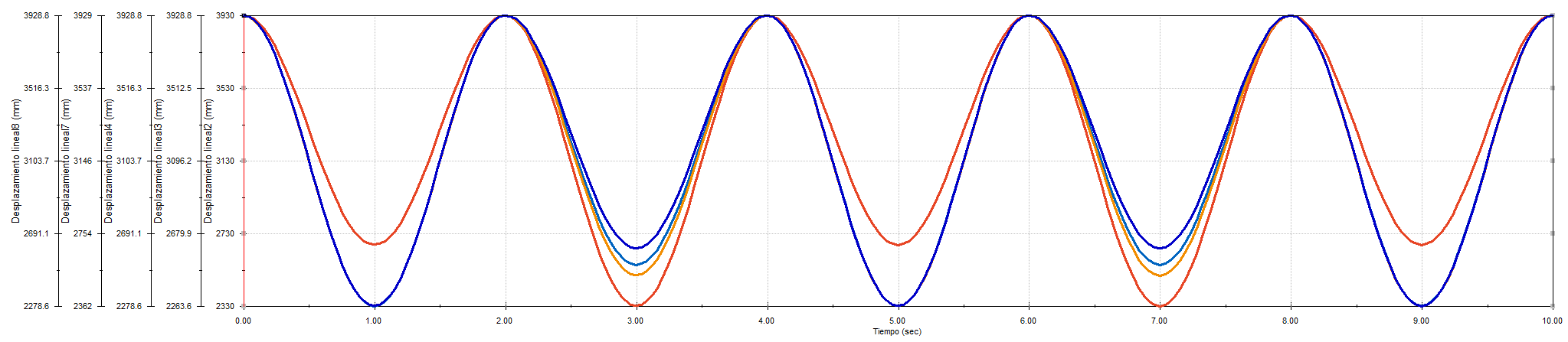
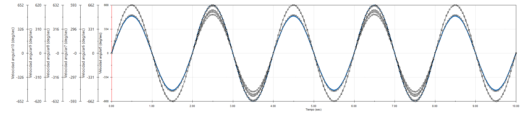
Chart 2 - Actuator RPM
Relates required actuation speed to RPM limit, used to validate screw lead and operating feasibility.